ads 728x90

Highlight

14S BMS Wiring Diagram: The Ultimate Guide for DIY Enthusiasts Wiring manual bms wiring diagram

Alright, fam, let's get into this BMS wiring situation. You know how crucial it is to have your power setup straight, especially when yo...

Saturday, April 26, 2025

Yamaha Command Link Wiring Diagram: Optimize Your Marine Electronics!

Are you ready to take your boating experience to the next level? Understanding the Yamaha Command Link wiring diagram is essential for optimizing your marine electronics and ensuring seamless communication between your boat's components. Whether you're a seasoned sailor or a weekend warrior, having a clear grasp of this wiring system can enhance your vessel's performance, improve safety, and make troubleshooting a breeze. In this blog post, we'll dive deep into the intricacies of the Yamaha Command Link wiring diagram, providing you with the knowledge you need to connect your electronics like a pro and enjoy every moment on the water!

Yamaha Command Link Wiring Diagram For 6y5

When it comes to optimizing your marine electronics, understanding the Yamaha Command Link wiring diagram for the 6Y5 display is crucial. This advanced system allows for seamless integration of various marine components, enhancing both functionality and performance. The wiring diagram provides a clear visual representation of how to connect the 6Y5 display to your Yamaha outboard motor, ensuring that you can monitor critical engine data, such as RPM, fuel consumption, and battery status, all in real-time. By following the wiring diagram accurately, you can avoid common installation pitfalls and ensure that your marine electronics operate smoothly, allowing you to focus on enjoying your time on the water. Whether you're a seasoned boater or a novice, mastering this wiring setup will significantly enhance your boating experience.

Yamaha command link wiring diagram for 6y5 www.wiringdigital.com

Yamaha Command Link Plus Wiring Diagrams The Hull Truth, 55% Off

When it comes to optimizing your marine electronics, understanding the Yamaha Command Link Plus wiring diagrams can make all the difference. These diagrams provide a clear and detailed layout for connecting your Yamaha engine to various marine devices, ensuring seamless communication and functionality. On forums like The Hull Truth, you can find valuable insights and shared experiences from fellow boaters who have successfully navigated the complexities of these wiring systems. Plus, with discounts of up to 55% off on select marine electronics, now is the perfect time to invest in the right tools and components to enhance your boating experience. Whether you're upgrading your navigation system or integrating new accessories, having access to accurate wiring diagrams is essential for a smooth installation process.

Yamaha command link plus wiring diagrams the hull truth, 55% off www.oceanproperty.co.th

Yamaha Command Link Wiring Diagram For 6y5

When it comes to optimizing your marine electronics, understanding the Yamaha Command Link wiring diagram for the 6Y5 display is crucial. This advanced system allows for seamless integration of various marine components, enhancing both functionality and performance. The wiring diagram provides a clear visual representation of how to connect the 6Y5 display to your Yamaha outboard motor, ensuring that you can monitor critical engine data, such as RPM, fuel consumption, and battery status, all in real-time. By following the wiring diagram accurately, you can avoid common installation pitfalls and ensure that your marine electronics operate smoothly, allowing you to focus on enjoying your time on the water. Whether you're a seasoned boater or a novice, mastering this wiring setup will significantly enhance your boating experience.

Yamaha command link wiring diagram for 6y5 www.wiringdigital.com

Yamaha Command Link Wiring Diagram

When it comes to optimizing your marine electronics, understanding the Yamaha Command Link wiring diagram is essential for seamless connectivity and functionality. This diagram serves as a comprehensive guide, illustrating how to effectively connect various components of your Yamaha marine system, including gauges, engines, and other electronic devices. By following the wiring diagram, boaters can ensure proper installation, minimize troubleshooting time, and enhance the overall performance of their marine setup. Whether you're upgrading your existing system or installing new gear, having a clear grasp of the Yamaha Command Link wiring diagram will empower you to maximize the capabilities of your marine electronics, ensuring a smoother and more enjoyable boating experience.

Yamaha command link wiring diagram dharmaraygen.blogspot.com

[diagram] Yamaha Command Link Wiring Diagram

When it comes to optimizing your marine electronics, understanding the Yamaha Command Link wiring diagram is essential. This diagram serves as a comprehensive guide for connecting various components of your Yamaha outboard system, ensuring seamless communication between your engine and onboard electronics. With a clear visual representation, you can easily identify the wiring paths for gauges, switches, and other critical devices, minimizing the risk of errors during installation. By following the Yamaha Command Link wiring diagram, you can enhance the performance of your marine setup, allowing for better monitoring and control of your vessel's systems. Whether you're a seasoned boater or a DIY enthusiast, mastering this diagram can significantly elevate your boating experience.

[diagram] yamaha command link wiring diagram mydiagram.online

Friday, April 25, 2025

Multi USB Charger Circuit: Charge All Your Devices At Once!

In today's fast-paced digital world, juggling multiple devices can be a challenge, especially when it comes to keeping them charged and ready to go. Enter the Multi USB Charger Circuit—a game-changing solution that allows you to charge all your devices at once, without the hassle of tangled cords or searching for multiple outlets. Whether you're at home, in the office, or on the go, this innovative circuit design not only maximizes efficiency but also ensures that your gadgets are powered up and ready for action. In this blog post, we'll explore the benefits of a Multi USB Charger Circuit, its components, and how you can build one to simplify your charging needs.

Building A Usb Charger Circuit

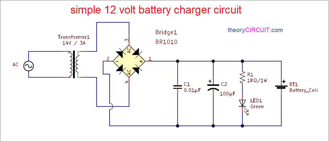
Building a USB charger circuit can be an exciting and rewarding project, especially when you want to charge multiple devices simultaneously. To create a multi USB charger circuit, you'll need a few essential components: a suitable power supply, USB ports, and a voltage regulator to ensure your devices receive the correct voltage. Start by designing a schematic that outlines how each component connects, ensuring that the power supply can handle the total current required by all devices. Once assembled, this circuit not only provides the convenience of charging multiple gadgets at once but also enhances your understanding of electronics and circuit design. By following safety precautions and testing your circuit thoroughly, you can create a reliable charger that meets your everyday needs.

Building a usb charger circuit www.thegeekpub.com

All-dock Wants To Charge All Your Devices, And Do It Incredibly Fast

In today's fast-paced world, staying connected means juggling multiple devices, from smartphones and tablets to smartwatches and wireless earbuds. All-dock recognizes this challenge and has engineered a solution that not only simplifies your charging needs but does so with remarkable speed. Imagine a single, sleek charging station that can power up all your devices simultaneously, eliminating the clutter of tangled cords and multiple chargers. With advanced technology designed to optimize charging efficiency, All-dock ensures that each device receives the right amount of power, allowing you to get back to what matters most without the frustrating wait. Say goodbye to low battery anxiety and hello to a seamless charging experience that keeps you powered up and ready to go!

All-dock wants to charge all your devices, and do it incredibly fast www.droid-life.com

Charge All Your Devices At Once With The Jackery Giant+ Portable

In today's fast-paced world, staying connected is essential, and the Jackery Giant+ portable charger makes it easier than ever to power up all your devices simultaneously. With its multi-USB charging capability, this powerhouse can juice up your smartphone, tablet, and other gadgets all at once, eliminating the hassle of juggling multiple chargers. Featuring a sleek design and a robust battery capacity, the Jackery Giant+ ensures that you won't run out of power when you need it most, whether you're at home, in the office, or on the go. Say goodbye to the clutter of tangled cords and hello to the convenience of charging everything you need with just one compact device!

Charge all your devices at once with the jackery giant+ portable www.popsugar.com

Alxum 120w Usb Charging Station For Multi Devices With Qc 3.0 Fast

The Alxum 120W USB Charging Station is a game-changer for anyone juggling multiple devices. With its impressive QC 3.0 fast charging capability, this station ensures that your smartphones, tablets, and other gadgets are powered up quickly and efficiently. Featuring multiple USB ports, it allows you to charge several devices simultaneously without sacrificing speed or performance. Whether you're at home, in the office, or on the go, the Alxum charging station provides a convenient and organized solution to keep all your devices ready for action. Say goodbye to cluttered cables and slow charging times—this powerful charging hub is designed to meet the demands of today's tech-savvy users.

Alxum 120w usb charging station for multi devices with qc 3.0 fast bigamart.com

New 10/20/40 Ports Multi Usb Intelligent Fast Charger Charging Station

In today's fast-paced world, staying connected is essential, and the New 10/20/40 Ports Multi USB Intelligent Fast Charger Charging Station is here to simplify your charging needs. This powerhouse charging station allows you to charge multiple devices simultaneously, making it perfect for families, offices, or anyone with a plethora of gadgets. With its intelligent fast-charging technology, it automatically detects and delivers the optimal charging speed for each device, ensuring efficient and safe power delivery. No more tangled cords or waiting for one device to charge before plugging in another—this charging station is designed to keep all your devices powered up and ready to go. Whether you're charging smartphones, tablets, or other USB-powered devices, the multi USB charger circuit is the ultimate solution for keeping your tech organized and fully charged.

New 10/20/40 ports multi usb intelligent fast charger charging station chileb.cl

Thursday, April 24, 2025

PCB Design Ground Plane: Essential Tips For Designers

When it comes to printed circuit board (PCB) design, the ground plane is often an overlooked yet crucial element that can significantly impact the performance and reliability of your circuit. A well-designed ground plane not only helps in reducing electromagnetic interference (EMI) but also enhances signal integrity and thermal management. Whether you're a seasoned designer or just starting out, understanding the nuances of ground plane design can elevate your projects to the next level. In this blog post, we'll explore essential tips and best practices that every PCB designer should consider to optimize their ground plane, ensuring a robust and efficient design.

Pcb-ground-plane-optimization-for-coreless-current-sensor-applications

When designing PCBs for coreless current sensor applications, optimizing the ground plane is crucial for achieving high performance and accuracy. A well-structured ground plane minimizes electromagnetic interference and enhances signal integrity, which is vital for precise current measurements. Designers should consider factors such as the ground plane's thickness, material, and layout to ensure uniform current distribution and reduce parasitic inductance. Additionally, strategically placing vias can help connect different layers while maintaining a low-impedance path, further improving the sensor's responsiveness. By focusing on ground plane optimization, PCB designers can significantly enhance the reliability and efficiency of coreless current sensor applications, leading to better overall system performance.

Pcb-ground-plane-optimization-for-coreless-current-sensor-applications www.allegromicro.com

Ground Plane: Multilayer Printed Circuit Boards (pcbs)

In the realm of PCB design, the ground plane serves as a critical component, particularly in multilayer printed circuit boards (PCBs). Acting as a common reference point for all electrical signals, the ground plane helps to minimize electromagnetic interference (EMI) and ensures signal integrity across the board. By providing a low-resistance path for return currents, it enhances the overall performance and stability of the circuit. Moreover, a well-designed ground plane can facilitate better thermal management and improve the reliability of the PCB, making it an essential consideration for designers. Understanding the intricacies of ground plane layout, including its thickness, material choice, and placement, can significantly impact the efficiency and effectiveness of your PCB design, ultimately leading to a more robust final product.

Ground plane: multilayer printed circuit boards (pcbs) madpcb.com

Power Supply Pcb Ground Plane And Thermal Vias

In PCB design, the ground plane is a critical component that significantly influences both electrical performance and thermal management. A well-designed ground plane provides a low-resistance path for return currents, which helps minimize electromagnetic interference and enhances signal integrity. Incorporating thermal vias into your design can further optimize heat dissipation by allowing heat generated by components to transfer efficiently to the ground plane. This combination not only aids in maintaining operational stability but also prolongs the lifespan of the PCB. By understanding the importance of a robust ground plane and the strategic placement of thermal vias, designers can create more reliable and efficient PCBs that meet the demands of modern electronics.

Power supply pcb ground plane and thermal vias electronics.stackexchange.com

Pcb Design Ground Plane Ground Plane Pcb: A Return Path For Circuit

In PCB design, the ground plane serves as a crucial return path for electrical signals, ensuring the stability and performance of the circuit. By providing a continuous conductive surface, the ground plane minimizes electromagnetic interference and reduces signal noise, which is essential for maintaining signal integrity. Additionally, it helps in thermal management by distributing heat evenly across the board. When designing a PCB, incorporating an effective ground plane can significantly enhance the overall functionality and reliability of the circuit, making it an essential consideration for designers aiming to create high-quality electronic devices.

Pcb design ground plane ground plane pcb: a return path for circuit pcbways.pages.dev

Mastering The Art Of Pcb Design Basics

Mastering the art of PCB design basics is crucial for any designer looking to create efficient and reliable printed circuit boards. Understanding the fundamentals, such as component placement, trace routing, and, importantly, the role of ground planes, sets the foundation for successful PCB layouts. A well-designed ground plane not only reduces electromagnetic interference but also improves signal integrity and thermal management. By focusing on these essential principles, designers can enhance their skills and produce PCBs that meet the demands of modern electronics, ensuring both performance and longevity in their designs. Whether you're a novice or an experienced engineer, refining your grasp of these basics will elevate your PCB design projects and contribute to your overall success in the field.

Mastering the art of pcb design basics www.protoexpress.com

Wednesday, April 23, 2025

Smeg Oven Wiring Diagram: Fix Your Oven Like A Pro

Are you tired of dealing with a malfunctioning Smeg oven? Whether it's a pesky heating issue or an unresponsive control panel, understanding your oven's wiring diagram can be the key to troubleshooting and fixing problems like a pro. In this blog post, we'll dive deep into the intricacies of the Smeg oven wiring diagram, providing you with valuable insights and step-by-step guidance to help you diagnose and repair common issues. Say goodbye to expensive repair bills and hello to the satisfaction of taking control of your kitchen appliance!

Smeg Oven Wiring Diagram

When it comes to troubleshooting your Smeg oven, understanding the wiring diagram is essential for any DIY enthusiast or home cook looking to fix their appliance like a pro. A Smeg oven wiring diagram provides a clear visual representation of the electrical components and their connections, making it easier to identify any issues related to power supply, heating elements, or control systems. By familiarizing yourself with the diagram, you can confidently tackle common problems such as faulty thermostats or broken heating elements, ensuring your oven operates efficiently and safely. Whether you're replacing parts or simply conducting routine maintenance, having access to a detailed wiring diagram can save you time and money, empowering you to take charge of your kitchen repairs.

Smeg oven wiring diagram art-rise1.blogspot.com

[diagram] Wiring Diagram For Smeg Oven

When it comes to troubleshooting your Smeg oven, having a clear and detailed wiring diagram is essential for diagnosing and fixing issues effectively. A wiring diagram for your Smeg oven provides a visual representation of the electrical components and their connections, making it easier for you to understand how the appliance operates. By following this diagram, you can identify potential faults, safely replace faulty parts, and ensure that all connections are secure. Whether you're dealing with power issues, faulty heating elements, or control panel malfunctions, a comprehensive wiring diagram will empower you to tackle repairs like a pro, saving you time and money in the process.

[diagram] wiring diagram for smeg oven wiringschema.com

Smeg Range Cooker Wiring Diagram

When tackling a Smeg range cooker wiring diagram, it's essential to understand the layout and connections that power your oven. A well-organized wiring diagram can help you identify the various components, such as the heating elements, thermostats, and control panels, making it easier to troubleshoot any issues. By following the diagram meticulously, you can ensure that each wire is correctly connected, preventing potential electrical hazards and ensuring optimal oven performance. Whether you're replacing a faulty part or simply performing routine maintenance, having a clear understanding of the wiring diagram will empower you to fix your Smeg oven like a pro, saving you time and money on repairs.

Smeg range cooker wiring diagram wiringdiagram.2bitboer.com

[diagram] Wiring Diagram Smeg Oven

When it comes to troubleshooting your Smeg oven, understanding the wiring diagram is crucial for effective repairs. A Smeg oven wiring diagram provides a clear visual representation of the electrical connections and components within the appliance, allowing you to identify potential issues with ease. Whether you're dealing with a faulty heating element, malfunctioning thermostat, or any other electrical problem, the diagram serves as a valuable guide for both novice DIYers and seasoned professionals. By following the wiring diagram, you can confidently navigate the complexities of your oven's electrical system, ensuring that you tackle repairs like a pro and restore your appliance to optimal working condition.

[diagram] wiring diagram smeg oven wiringschema.com

Smeg Range Cooker Wiring Diagram

When tackling a Smeg range cooker wiring diagram, it's essential to understand the layout and connections that power your oven. A well-organized wiring diagram can help you identify the various components, such as the heating elements, thermostats, and control panels, making it easier to troubleshoot any issues. By following the diagram meticulously, you can ensure that each wire is correctly connected, preventing potential electrical hazards and ensuring optimal oven performance. Whether you're replacing a faulty part or simply performing routine maintenance, having a clear understanding of the wiring diagram will empower you to fix your Smeg oven like a pro, saving you time and money on repairs.

Smeg range cooker wiring diagram wiringdiagram.2bitboer.com