
Exploring the fascinating world of timer circuits, we delve into the intricacies of time-delayed operations. These circuits, fundamental building blocks in electronics, offer the ability to control events with precision, activating or deactivating components after a specific duration. From simple on-delay mechanisms to sophisticated speaker delay systems, the applications are vast and impactful across numerous industries.
On Delay Timer Circuit Diagram

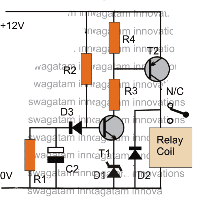
The on-delay timer circuit is a common type, designed to energize an output only after a predetermined time has elapsed from the initial trigger. The basic principle involves charging a capacitor through a resistor. When the input signal is received, the capacitor begins to accumulate charge. The voltage across the capacitor gradually increases until it reaches a threshold voltage. Once this threshold is reached, the output is activated, enabling the controlled device or process. The duration of the delay is determined by the values of the resistor and capacitor, providing flexibility in tailoring the timing to specific requirements.
These circuits find application in a wide range of scenarios. For instance, in industrial automation, on-delay timers are used to sequence operations, ensuring that machines start up in a specific order to prevent overload or damage. Consider a conveyor belt system where different sections need to activate sequentially; an on-delay timer can ensure each section starts after the previous one has reached full speed. In lighting systems, they can delay turning on lights to conserve energy or create a more gradual illumination effect. In security systems, an on-delay timer can prevent false alarms by waiting for a certain period before activating the alarm system, allowing time for authorized personnel to disarm the system.
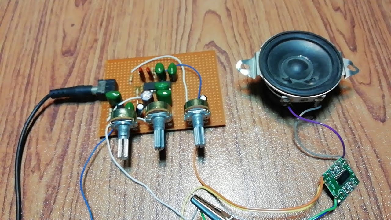
Simple Speaker Delay Circuit

Moving beyond simple on-delay timers, the speaker delay circuit introduces a more nuanced application of time delay principles. These circuits are predominantly used in audio systems, particularly in home theater or sound reinforcement setups, to synchronize the sound output from different speakers. The objective is to ensure that the sound from all speakers reaches the listener simultaneously, regardless of their distance from the listener.
The functionality of a speaker delay circuit stems from the fact that sound travels at a finite speed. Consequently, speakers positioned farther away from the listener will have a delayed sound arrival time compared to those closer. To compensate for this discrepancy, a speaker delay circuit introduces a precisely calibrated delay to the signal sent to the closer speakers. This allows the sound from the farther speakers to "catch up," resulting in a cohesive and synchronized audio experience. The delay is typically achieved using digital signal processing (DSP) techniques, allowing for fine-grained control and adjustment. Modern speaker delay circuits often incorporate sophisticated algorithms to account for room acoustics and speaker characteristics, further enhancing the synchronization and overall audio quality.
Applications for speaker delay circuits are diverse. In home theater systems, they are crucial for creating a realistic and immersive surround sound experience. By properly calibrating the delay, the listener perceives the sound effects as originating from the correct locations in the sound field. In large venues such as concert halls or stadiums, speaker delay circuits are essential for ensuring that the sound from all speakers arrives at the listeners' ears at the same time, preventing echoes and maintaining clarity. Moreover, in professional recording studios, speaker delay circuits can be used to create artificial reverb or echo effects, adding depth and ambiance to the recorded sound.
If you are searching about Analog Delay Schematic Diagram - Circuit Diagram you've visit to the right web. We have 25 Pics about Analog Delay Schematic Diagram - Circuit Diagram like On Delay Timer Connection Diagram - YouTube, ON Delay OFF Delay Timer Connection - YouTube and also Don't Make A Sound With A Twist [Pizza Tower] [Mods]. Here you go:
Analog Delay Schematic Diagram - Circuit Diagram
 www.circuitdiagram.co
 Audio Delay Circuit Diagram
 wirepartnotaryship.z22.web.core.windows.net
 On Delay Timer Circuit Diagram - Wiring Diagram
www.organised-sound.com Animal Sounds Esl Printable Vocabulary Learning Cards - Vrogue.co
 www.vrogue.co
 How Does Sound Travel
 nl.venngage.com
 ON Delay OFF Delay Timer Connection - YouTube
 www.youtube.com
 Lesson 7 Describing Characters In Plays Answer Key - Vrogue.co
 www.vrogue.co
 What Is Delay Circuit Meaning - Circuit Diagram
 www.circuitdiagram.co
 Don't Make A Sound With A Twist [Pizza Tower] [Mods]
![Don't Make A Sound With A Twist [Pizza Tower] [Mods]](https://images.gamebanana.com/img/ss/mods/640bee6248a00.jpg) gamebanana.com
gamebanana.com Irányítószám Szükségletek Bejegyzés 4 Pin Sound Sensor Arduino Ok
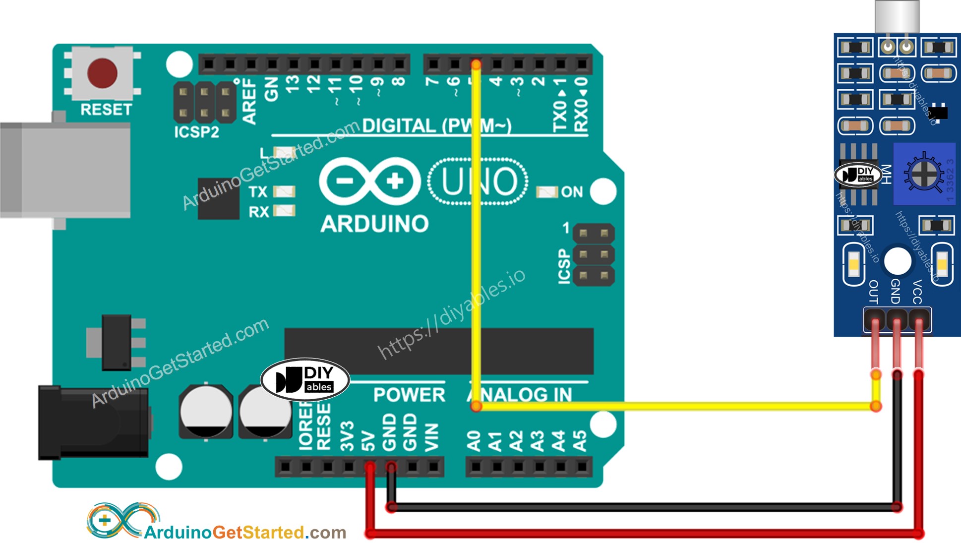 brashind.com
 Wiring Diagram For Timer Relay » Wiring Digital And Schematic
 www.wiringdigital.com
 HOW TO MAKE SOUND DELAY CIRCUIT LIVE ECHO PT2399 IC | @ETElectricalTech
 www.youtube.com
 HOW TO MAKE SOUND DELAY CIRCUIT | LIVE ECHO - YouTube
 www.youtube.com
 delay circuit echo make sound how
The RC Delay Element
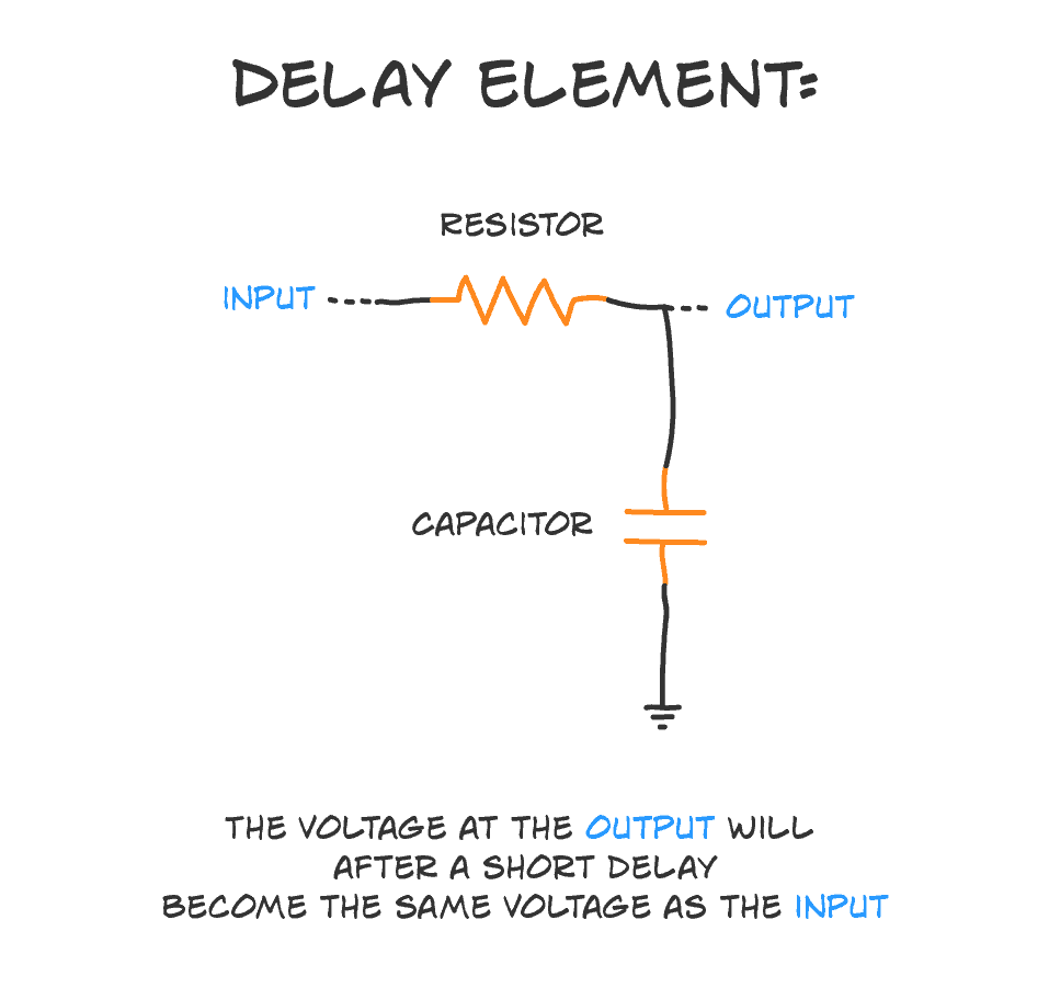 www.build-electronic-circuits.com
 delay rc element how electronic circuits does build work
Simple Time Delay Circuit
 usermanualperidium.z21.web.core.windows.net
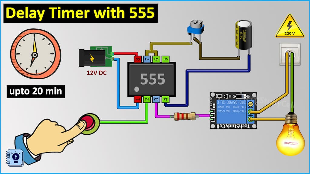
 Time Delay Circuit Using 555 Timer
 fixwiringhoarsens.z13.web.core.windows.net
 On Delay Timer Connection Diagram - YouTube
 www.youtube.com
 Simple Timer Circuit Schematic - Circuit Diagram
 www.circuitdiagram.co
 Simple Speaker Delay Circuit
www.circuits-diy.com How To Make On-Off Delay Timer Connection With Contactor | 3 Phase
 www.youtube.com
 3D Sound Audio Delay
 electronics-diy.com
 audio delay schematic
555 Timer
 easyelectronicsproject.com
 Timer On Delay And Off Delay Explained | How Timers Work | Electreca
 www.youtube.com
 On Time Delay Circuit Diagram » Wiring Diagram
 www.diagramelectric.co
 Transistor Delay Circuit | The Blog Of A Gypsy Engineer
 blog.gypsyengineer.com
 3d sound audio delay. Analog delay schematic diagram. The rc delay element