ads 728x90

Highlight

14S BMS Wiring Diagram: The Ultimate Guide for DIY Enthusiasts Wiring manual bms wiring diagram

Alright, fam, let's get into this BMS wiring situation. You know how crucial it is to have your power setup straight, especially when yo...

Monday, April 28, 2025

1969 GTO Wiring Diagram: The Ultimate Guide For Classic Car Enthusiasts

If you're a classic car enthusiast, few vehicles evoke as much nostalgia and admiration as the 1969 Pontiac GTO. Known for its powerful performance and iconic design, this muscle car has left an indelible mark on automotive history. However, restoring or maintaining a GTO can present its own set of challenges, especially when it comes to understanding its intricate wiring system. In this ultimate guide, we'll delve into the 1969 GTO wiring diagram, providing you with essential insights and detailed information to help you navigate the complexities of your classic ride. Whether you're a seasoned restorer or a newcomer to the world of vintage cars, this comprehensive resource will ensure your GTO runs smoothly and looks stunning for years to come.

Classiccarwiring 65 Gto Wiring Diagram Errors

When it comes to restoring a classic like the 1969 GTO, having an accurate wiring diagram is essential, and that's where Classiccarwiring's 65 GTO wiring diagram can lead to some confusion. Many enthusiasts have reported discrepancies in the color codes and wire placements, which can result in frustrating troubleshooting and potential electrical issues down the line. It's crucial for classic car enthusiasts to cross-reference these diagrams with factory manuals or trusted resources to ensure that every connection is correct. By being aware of these common errors, you can save yourself time and headaches during your restoration project, ensuring that your GTO not only looks great but also runs smoothly.

Classiccarwiring 65 gto wiring diagram errors www.gtoforum.com

1967 Pontiac Gto Wiring Diagram

When it comes to restoring or maintaining a classic muscle car like the 1969 Pontiac GTO, having access to accurate wiring diagrams is essential. The 1967 Pontiac GTO wiring diagram serves as a valuable reference, offering insights into the electrical systems that paved the way for the iconic design of the 1969 model. While the two years share similarities, understanding the nuances in wiring can help enthusiasts troubleshoot issues more effectively and ensure that every component—from headlights to ignition—functions seamlessly. By examining the 1967 diagram, owners can gain a deeper appreciation for the evolution of the GTO's electrical layout, making it easier to navigate any restoration project or upgrade. Whether you're a seasoned mechanic or a first-time restorer, this knowledge is crucial for preserving the legacy of one of America's most beloved muscle cars.

1967 pontiac gto wiring diagram stewart-switch.com

1969 Jeepmando Wiring Diagram

When restoring or maintaining a classic car like the 1969 GTO, having a reliable wiring diagram is essential, and the 1969 Jeep Mando wiring diagram can provide valuable insights. Although primarily associated with Jeep vehicles, the Mando wiring system features components and layouts that can be beneficial for GTO enthusiasts looking to understand the electrical intricacies of their ride. By comparing the Jeep Mando diagram with the GTO's wiring, classic car lovers can gain a clearer understanding of how different systems interact, troubleshoot electrical issues more effectively, and ensure that their restoration projects stay true to the original specifications. Whether you're working on the ignition system, lighting, or accessories, integrating knowledge from the Jeep Mando wiring diagram can enhance your overall restoration experience.

1969 jeepmando wiring diagram wiringdiagramfun.z19.web.core.windows.net

1965 Gto Dash Wiring Diagram

When restoring or maintaining a classic 1965 GTO, understanding the dash wiring diagram is crucial for ensuring that all electrical components function properly. The dash wiring diagram provides a detailed visual representation of the electrical system, illustrating how various components, such as the gauges, lights, and ignition system, are interconnected. This diagram not only aids in troubleshooting electrical issues but also serves as an invaluable resource for anyone looking to upgrade or modify their vehicle's interior. By familiarizing yourself with the 1965 GTO dash wiring diagram, you can confidently tackle wiring repairs and enhancements, ensuring that your classic car remains in peak condition while preserving its authenticity.

1965 gto dash wiring diagram art-gram.blogspot.com

Wiring Diagram For 1966 Pontiac Gto

When it comes to restoring or maintaining a classic car like the 1966 Pontiac GTO, having an accurate wiring diagram is essential for ensuring everything operates smoothly. The wiring diagram serves as a visual representation of the electrical system, detailing the connections and components that make up the vehicle's circuitry. For enthusiasts tackling projects on their 1966 GTO, this diagram can be invaluable, helping to troubleshoot issues, replace faulty wiring, or even upgrade the electrical system. Understanding the layout of the wiring can save time and prevent costly mistakes, making it a crucial tool for anyone looking to preserve the performance and authenticity of this iconic muscle car.

Wiring diagram for 1966 pontiac gto www.wiringcore.com

Sunday, April 27, 2025

700 HR52TA17 Wiring Diagram: The Ultimate Guide For Technicians

Welcome to our ultimate guide on the 700 HR52TA17 wiring diagram, a crucial resource for technicians and DIY enthusiasts alike. Whether you're troubleshooting an existing system or embarking on a new installation, understanding the intricacies of this wiring diagram is essential for ensuring optimal performance and safety. In this post, we'll break down the key components, provide step-by-step instructions, and offer expert tips to help you navigate the complexities of the 700 HR52TA17. Get ready to enhance your technical skills and boost your confidence in handling wiring projects with ease!

Allen-bradley 700 Relay Wiring Diagram Allen Bradley 700 Rel

In the realm of industrial automation, understanding the Allen-Bradley 700 relay wiring diagram is crucial for technicians working with the 700 HR52TA17 relay. This reliable component is designed for various control applications, and a clear wiring diagram simplifies installation and troubleshooting processes. The diagram typically illustrates the terminal connections, showing how to properly wire the relay to ensure optimal performance. By following the wiring instructions meticulously, technicians can avoid common pitfalls and ensure that the relay operates efficiently within the control circuit. Whether you're a seasoned professional or a novice, mastering the wiring diagram of the Allen-Bradley 700 relay is an essential skill that enhances your troubleshooting capabilities and ensures the longevity of your automation systems.

Allen-bradley 700 relay wiring diagram allen bradley 700 rel daninojzf2guidefix.z13.web.core.windows.net

How To Wire An Allen Bradley 700-hr52ta17: Complete Wiring Diagram

Wiring the Allen Bradley 700-HR52TA17 relay requires a clear understanding of its connections to ensure optimal performance in your control circuit. Begin by identifying the terminals on the relay: the coil terminals typically labeled A1 and A2, and the contact terminals which correspond to the specific application needs. For a complete wiring diagram, connect the coil terminals to your control voltage source, ensuring that the polarity is correct if applicable. Next, wire the load to the appropriate contact terminals, paying attention to the configuration of normally open (NO) or normally closed (NC) contacts based on your system requirements. It's crucial to refer to the manufacturer's specifications for detailed wiring instructions and safety precautions. By following these steps, technicians can efficiently integrate the 700-HR52TA17 into their systems, ensuring reliable operation and functionality.

How to wire an allen bradley 700-hr52ta17: complete wiring diagram autoctrls.com

Allen Bradley 700 Hr52ta17 Wiring Diagram

The Allen Bradley 700 HR52TA17 is a vital component in industrial control systems, and understanding its wiring diagram is essential for technicians working with these devices. This specific model features a versatile design that allows for various configurations, making it crucial to refer to the correct wiring diagram to ensure proper installation and functionality. In this ultimate guide, we will delve into the wiring diagram specifics, including terminal connections, power supply requirements, and troubleshooting tips. By following the detailed instructions and diagrams provided, technicians can optimize the performance of the 700 HR52TA17, ensuring reliable operation in demanding industrial environments.

Allen bradley 700 hr52ta17 wiring diagram blog-fitz.blogspot.com

[diagram] Polaris 700 Wiring Diagram Free

When it comes to troubleshooting and repairing the Polaris 700, having access to a detailed wiring diagram is essential for technicians. The Polaris 700 wiring diagram, especially the HR52TA17 model, provides a comprehensive visual representation of the electrical system, helping professionals understand the intricate connections and components. Fortunately, there are free resources available online that offer high-quality diagrams, making it easier for technicians to diagnose issues and perform repairs efficiently. By utilizing these wiring diagrams, technicians can save time and ensure that they are following the correct procedures, ultimately leading to a smoother repair process and enhanced vehicle performance. Whether you're a seasoned mechanic or a DIY enthusiast, having the right wiring diagram at your fingertips can make all the difference in your repair endeavors.

[diagram] polaris 700 wiring diagram free mydiagram.online

Step-by-step Guide: Wiring Diagram For Allen Bradley 700-ha32z24

In this step-by-step guide, we will delve into the wiring diagram for the Allen Bradley 700-HA32Z24 relay, a crucial component for technicians working with the 700 HR52TA17 system. Understanding the wiring configuration is essential for ensuring proper installation and functionality. We'll break down the diagram into manageable sections, detailing each terminal connection and its corresponding function. This comprehensive approach will help you troubleshoot issues effectively and enhance your overall efficiency when working with the 700 HR52TA17. Whether you're a seasoned technician or just starting, this guide will equip you with the knowledge you need to navigate the complexities of the wiring diagram with confidence.

Step-by-step guide: wiring diagram for allen bradley 700-ha32z24 design1systems.com

Saturday, April 26, 2025

Yamaha Command Link Wiring Diagram: Optimize Your Marine Electronics!

Are you ready to take your boating experience to the next level? Understanding the Yamaha Command Link wiring diagram is essential for optimizing your marine electronics and ensuring seamless communication between your boat's components. Whether you're a seasoned sailor or a weekend warrior, having a clear grasp of this wiring system can enhance your vessel's performance, improve safety, and make troubleshooting a breeze. In this blog post, we'll dive deep into the intricacies of the Yamaha Command Link wiring diagram, providing you with the knowledge you need to connect your electronics like a pro and enjoy every moment on the water!

Yamaha Command Link Wiring Diagram For 6y5

When it comes to optimizing your marine electronics, understanding the Yamaha Command Link wiring diagram for the 6Y5 display is crucial. This advanced system allows for seamless integration of various marine components, enhancing both functionality and performance. The wiring diagram provides a clear visual representation of how to connect the 6Y5 display to your Yamaha outboard motor, ensuring that you can monitor critical engine data, such as RPM, fuel consumption, and battery status, all in real-time. By following the wiring diagram accurately, you can avoid common installation pitfalls and ensure that your marine electronics operate smoothly, allowing you to focus on enjoying your time on the water. Whether you're a seasoned boater or a novice, mastering this wiring setup will significantly enhance your boating experience.

Yamaha command link wiring diagram for 6y5 www.wiringdigital.com

Yamaha Command Link Plus Wiring Diagrams The Hull Truth, 55% Off

When it comes to optimizing your marine electronics, understanding the Yamaha Command Link Plus wiring diagrams can make all the difference. These diagrams provide a clear and detailed layout for connecting your Yamaha engine to various marine devices, ensuring seamless communication and functionality. On forums like The Hull Truth, you can find valuable insights and shared experiences from fellow boaters who have successfully navigated the complexities of these wiring systems. Plus, with discounts of up to 55% off on select marine electronics, now is the perfect time to invest in the right tools and components to enhance your boating experience. Whether you're upgrading your navigation system or integrating new accessories, having access to accurate wiring diagrams is essential for a smooth installation process.

Yamaha command link plus wiring diagrams the hull truth, 55% off www.oceanproperty.co.th

Yamaha Command Link Wiring Diagram For 6y5

When it comes to optimizing your marine electronics, understanding the Yamaha Command Link wiring diagram for the 6Y5 display is crucial. This advanced system allows for seamless integration of various marine components, enhancing both functionality and performance. The wiring diagram provides a clear visual representation of how to connect the 6Y5 display to your Yamaha outboard motor, ensuring that you can monitor critical engine data, such as RPM, fuel consumption, and battery status, all in real-time. By following the wiring diagram accurately, you can avoid common installation pitfalls and ensure that your marine electronics operate smoothly, allowing you to focus on enjoying your time on the water. Whether you're a seasoned boater or a novice, mastering this wiring setup will significantly enhance your boating experience.

Yamaha command link wiring diagram for 6y5 www.wiringdigital.com

Yamaha Command Link Wiring Diagram

When it comes to optimizing your marine electronics, understanding the Yamaha Command Link wiring diagram is essential for seamless connectivity and functionality. This diagram serves as a comprehensive guide, illustrating how to effectively connect various components of your Yamaha marine system, including gauges, engines, and other electronic devices. By following the wiring diagram, boaters can ensure proper installation, minimize troubleshooting time, and enhance the overall performance of their marine setup. Whether you're upgrading your existing system or installing new gear, having a clear grasp of the Yamaha Command Link wiring diagram will empower you to maximize the capabilities of your marine electronics, ensuring a smoother and more enjoyable boating experience.

Yamaha command link wiring diagram dharmaraygen.blogspot.com

[diagram] Yamaha Command Link Wiring Diagram

When it comes to optimizing your marine electronics, understanding the Yamaha Command Link wiring diagram is essential. This diagram serves as a comprehensive guide for connecting various components of your Yamaha outboard system, ensuring seamless communication between your engine and onboard electronics. With a clear visual representation, you can easily identify the wiring paths for gauges, switches, and other critical devices, minimizing the risk of errors during installation. By following the Yamaha Command Link wiring diagram, you can enhance the performance of your marine setup, allowing for better monitoring and control of your vessel's systems. Whether you're a seasoned boater or a DIY enthusiast, mastering this diagram can significantly elevate your boating experience.

[diagram] yamaha command link wiring diagram mydiagram.online

Friday, April 25, 2025

Multi USB Charger Circuit: Charge All Your Devices At Once!

In today's fast-paced digital world, juggling multiple devices can be a challenge, especially when it comes to keeping them charged and ready to go. Enter the Multi USB Charger Circuit—a game-changing solution that allows you to charge all your devices at once, without the hassle of tangled cords or searching for multiple outlets. Whether you're at home, in the office, or on the go, this innovative circuit design not only maximizes efficiency but also ensures that your gadgets are powered up and ready for action. In this blog post, we'll explore the benefits of a Multi USB Charger Circuit, its components, and how you can build one to simplify your charging needs.

Building A Usb Charger Circuit

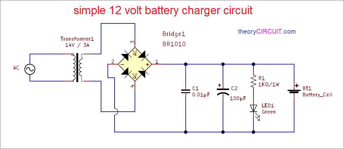
Building a USB charger circuit can be an exciting and rewarding project, especially when you want to charge multiple devices simultaneously. To create a multi USB charger circuit, you'll need a few essential components: a suitable power supply, USB ports, and a voltage regulator to ensure your devices receive the correct voltage. Start by designing a schematic that outlines how each component connects, ensuring that the power supply can handle the total current required by all devices. Once assembled, this circuit not only provides the convenience of charging multiple gadgets at once but also enhances your understanding of electronics and circuit design. By following safety precautions and testing your circuit thoroughly, you can create a reliable charger that meets your everyday needs.

Building a usb charger circuit www.thegeekpub.com

All-dock Wants To Charge All Your Devices, And Do It Incredibly Fast

In today's fast-paced world, staying connected means juggling multiple devices, from smartphones and tablets to smartwatches and wireless earbuds. All-dock recognizes this challenge and has engineered a solution that not only simplifies your charging needs but does so with remarkable speed. Imagine a single, sleek charging station that can power up all your devices simultaneously, eliminating the clutter of tangled cords and multiple chargers. With advanced technology designed to optimize charging efficiency, All-dock ensures that each device receives the right amount of power, allowing you to get back to what matters most without the frustrating wait. Say goodbye to low battery anxiety and hello to a seamless charging experience that keeps you powered up and ready to go!

All-dock wants to charge all your devices, and do it incredibly fast www.droid-life.com

Charge All Your Devices At Once With The Jackery Giant+ Portable

In today's fast-paced world, staying connected is essential, and the Jackery Giant+ portable charger makes it easier than ever to power up all your devices simultaneously. With its multi-USB charging capability, this powerhouse can juice up your smartphone, tablet, and other gadgets all at once, eliminating the hassle of juggling multiple chargers. Featuring a sleek design and a robust battery capacity, the Jackery Giant+ ensures that you won't run out of power when you need it most, whether you're at home, in the office, or on the go. Say goodbye to the clutter of tangled cords and hello to the convenience of charging everything you need with just one compact device!

Charge all your devices at once with the jackery giant+ portable www.popsugar.com

Alxum 120w Usb Charging Station For Multi Devices With Qc 3.0 Fast

The Alxum 120W USB Charging Station is a game-changer for anyone juggling multiple devices. With its impressive QC 3.0 fast charging capability, this station ensures that your smartphones, tablets, and other gadgets are powered up quickly and efficiently. Featuring multiple USB ports, it allows you to charge several devices simultaneously without sacrificing speed or performance. Whether you're at home, in the office, or on the go, the Alxum charging station provides a convenient and organized solution to keep all your devices ready for action. Say goodbye to cluttered cables and slow charging times—this powerful charging hub is designed to meet the demands of today's tech-savvy users.

Alxum 120w usb charging station for multi devices with qc 3.0 fast bigamart.com

New 10/20/40 Ports Multi Usb Intelligent Fast Charger Charging Station

In today's fast-paced world, staying connected is essential, and the New 10/20/40 Ports Multi USB Intelligent Fast Charger Charging Station is here to simplify your charging needs. This powerhouse charging station allows you to charge multiple devices simultaneously, making it perfect for families, offices, or anyone with a plethora of gadgets. With its intelligent fast-charging technology, it automatically detects and delivers the optimal charging speed for each device, ensuring efficient and safe power delivery. No more tangled cords or waiting for one device to charge before plugging in another—this charging station is designed to keep all your devices powered up and ready to go. Whether you're charging smartphones, tablets, or other USB-powered devices, the multi USB charger circuit is the ultimate solution for keeping your tech organized and fully charged.

New 10/20/40 ports multi usb intelligent fast charger charging station chileb.cl